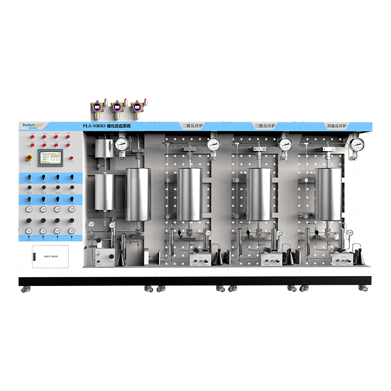
In flue gas denitrification (SNCR/SCR) experiments, most researchers still rely on a self-built setup consisting of “gas cylinders + mass flow controllers + bubbler + tube furnace”. This approach is flexible and low in cost, but in practice it is difficult to avoid certain structural shortcomings:
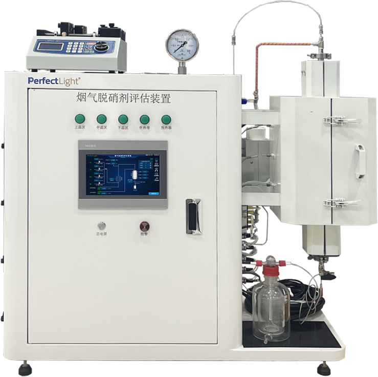
To address these systematic deviations, Perfectlight has introduced a standardised flue gas DeNOx catalyst evaluation system, designed to achieve precise control of the entire process from gas distribution to reaction.
1. Stable wide temperature range up to 1000 °C and a 200 mm long isothermal zone for true activity. The reaction unit adopts three-stage independent temperature control covering RT–1000 °C, with an isothermal zone 200 mm long. For reactions that are extremely sensitive to the temperature window, such as SNCR, a stable temperature and sufficient gas residence time are the core variables determining conversion. A 200 mm isothermal zone significantly increases the tolerance for the packed sample and the effective residence time of the reaction gas in the reaction zone, effectively eliminating heat-transfer artefacts caused by temperature gradients and providing a guarantee for obtaining true reaction kinetics data.
2. Real flue gas simulation with in-situ direct-injection mixing, overcoming both water-vapour condensation and urea crystallisation. Real industrial flue gas is often at high temperature and high humidity. The system’s preheating, vaporisation and full-line heat tracing eliminate water-vapour condensation in the pipeline at source, ensuring that the humidity (H2O concentration) reaching the catalyst bed is absolutely stable. More importantly, to address the pain point that liquid reductants such as urea and ammonia water readily crystallise and block the tube when preheated, the system abandons the traditional pipeline pre-mixing approach and adopts an “in-situ injection into the reactor” design. The reductant solution is introduced directly into the core reaction zone and dispersed efficiently, mixing instantly and spatially with the incoming high-temperature flue gas. This design both avoids crystallisation and blockage in the upstream pipeline and ensures a highly accurate NSR for the reaction.
3. Independent gas distribution plus precise liquid injection for accurate reaction boundaries. The gas feed is equipped with four independent MFCs as standard, with a control accuracy of 1% F.S., ensuring stable and smooth output of complex simulated flue gas; the liquid feed uses a dual-channel precision syringe pump with a feeding accuracy of up to 0.5%, ensuring high batch-to-batch consistency of trace reductant.
4. Tail-gas absorption plus PLC automatic control for laboratory safety. The tail end is fitted with an absorption-bottle tail-gas treatment unit that treats residual NOx, NH3 and other harmful components before discharge, meeting laboratory safety requirements. The control system uses a 10-inch touch screen with PLC programming, supporting temperature programme setting, and saving and recalling of flow parameters, reducing manual operating errors.