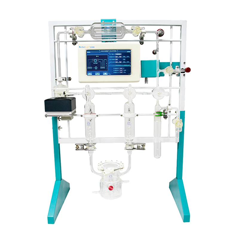
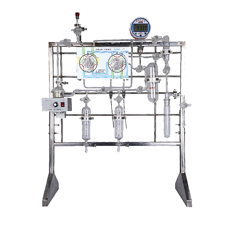
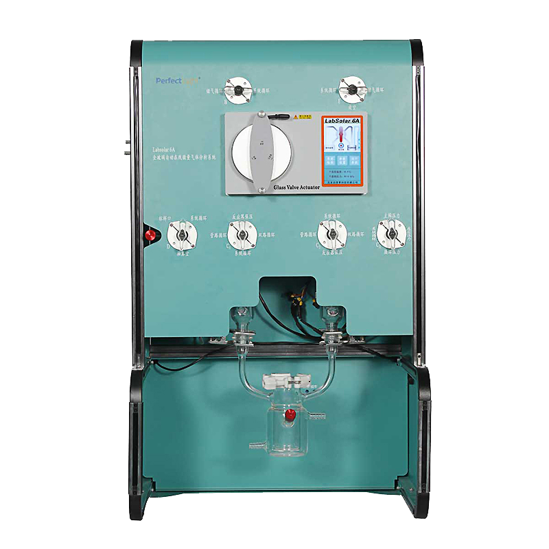
μGAS1001 Trace Gas Reaction Evaluation System is an experimental instrument developed by Bofeilai Technology based on years of R&D experience in airtight glass reaction systems, designed to meet customers' photocatalysis experiment needs. It is a catalytic activity evaluation system suitable for catalytic reactions that produce trace gases, such as photocatalytic overall water splitting and photocatalytic CO₂ reduction. The main body integrates a control unit, gas circulation module, automatic sampling module, and reactor module.
The operation end is controlled by a local controller (lower computer), offering powerful functionality and easy operation;
Can be equipped with quantitative loops of different volumes; sensitivity can be adjusted according to gas production to meet trace gas detection requirements;
Quantitative loop volumes: 0.5 mL, 1 mL, 2 mL, 3 mL, 5 mL optional; total system volume 440 mL; maximum sampling ratio 88:1;
New structural design with high gas tightness; dynamic oxygen leak rate < 0.1 μmol/h, meeting the requirements for measuring apparent quantum yield in photocatalytic overall water splitting;
Calibration curve linear regression R2 > 0.999; for four consecutive injections of the same concentration, RSD < 3%; accuracy reaches scientific-grade level;
Patented sampling valve island enables fully automated online carrier gas introduction, effectively avoiding air interference;
The controller features fully automatic dynamic leak testing so airtightness can be checked at any time.
Photocatalytic/Photoelectrocatalytic CO₂ Reduction
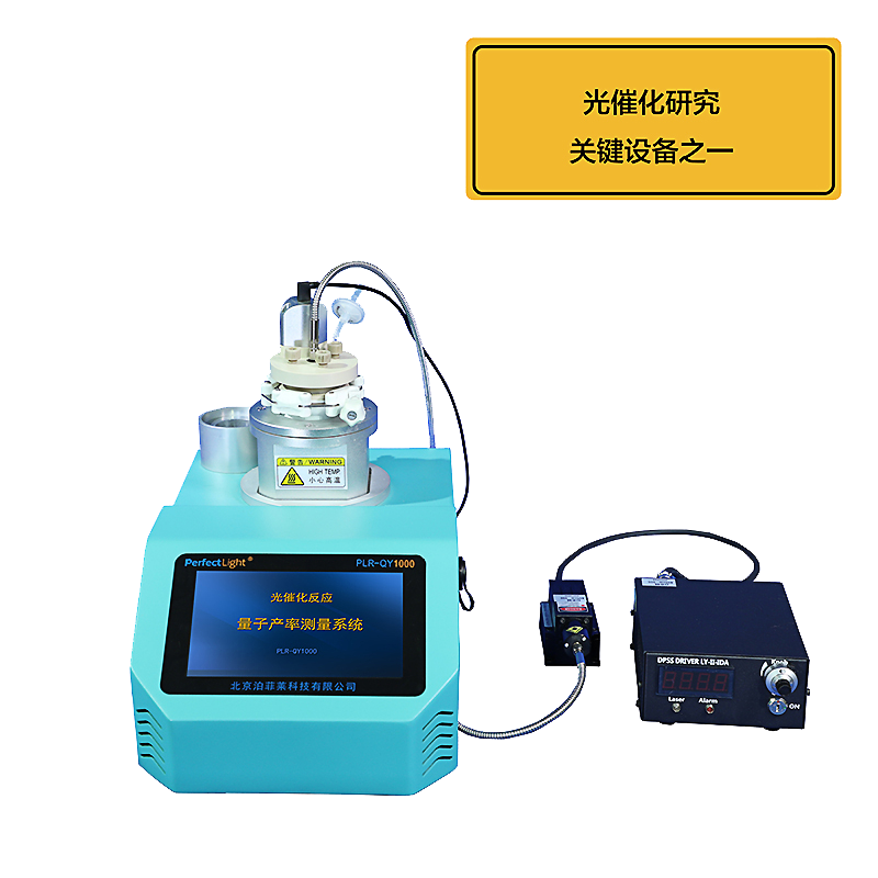
Photocatalytic Apparent Quantum Efficiency Testing
Photocatalytic Overall Water Splitting
Photocatalytic Oxygen Evolution Testing
Photocatalytic Hydrogen Production
PEC Photoelectrocatalytic Water Splitting
Electrocatalytic Water Splitting
| Product Parameters | |||
| Software Control Unit 7-inch LCD screen, real-time display of system pressure, ambient temperature, and humidity; Controlled by upper-computer software, simple operation; Complete experimental parameter recording and real-time storage of process parameters (reaction temperature, pressure, etc.); paperless experimental records; exportable results; Built-in calculation methods to read detection device data and directly display reaction rate and other parameters; Equipped with fully automatic dynamic airtightness testing for real-time monitoring; Built-in instrument methods control the sampling valve island for fully automatic online sampling, injection, and background gas introduction; Software can directly control the start/stop of gas chromatograph and vacuum pump; System can be preheated to avoid valve seizure caused by vacuum grease solidification; |
|||
| System Piping | |||
| Absolute Vacuum Degree | ≤0.5 kPa, based on absolute zero, eliminating pressure gauge fluctuations caused by temperature and humidity changes; | Operating Pressure Range | 0 kPa~Atmospheric Pressure |
| Airtightness | ≤0.1 μmol/h @O₂, meeting requirements for photocatalytic overall water-splitting apparent quantum efficiency testing; | Piping Material | Borosilicate glass, highly chemically inert, non-adsorptive |
| Valve Technology | Borosilicate glass material (no metal components), precision lapped surfaces | Number of Valves | 3 |
| Vacuum Grease | Imported Apiezon H high-temperature vacuum grease, chemically resistant, low vapor pressure, low volatility, working temperature: -10℃ to +200℃ | Total System Volume | 440 mL; reactor volume 210 mL; recommended working volume 40~80 mL |
| Piping Temperature Control | Circulation and sampling pipelines are temperature-controllable, max. 200℃ | Condenser | Fully condenses vapor to prevent water vapor from entering the gas chromatograph or vacuum pump, extending their service life |
| Fully Automatic Sampling Module | |||
| Sampling Method | Sampling module integrated into system (non-chromatographic), effectively shortening circulation path and improving gas mixing efficiency; | Quantitative Loop | Standard 2 mL, optional 0.5 mL, 1 mL, 3 mL, 5 mL, adjustable sensitivity |
| Maximum Sampling Ratio | 1:88, high sensitivity, suitable for trace gas detection | Automatic Background Gas Injection | • Precisely controls background gas injection volume to enhance circulation; • Effectively avoids air interference caused by needle-type injection; |
| Carrier Gas Pressure Range | Up to 0.5 MPa, compatible with complex GC configurations | Reaction Parameter Measurement Accuracy | Pressure: 1 Pa; Temperature: 0.01℃ |
| Gas Circulation Parameters | |||
| Gas Mixing Time | H₂ and O₂ mixing time <10 min | Linearity | Standard curve linear regression R²>0.999 |
| Repeatability | Four consecutive injections at same concentration, RSD<3% | Passive Magnetic Fan Pump | No electrical wiring, no hydrogen explosion risk, no interference from electrolytic hydrogen evolution |
| Sampling Mode | Patented sampling valve island; fully automatic online sampling module integrated within the system (non-chromatographic) | Circulation Piping | All circulation pipelines made of borosilicate glass; narrow pipeline inner diameter 3 mm; non-chromatographic small tubing; low gas resistance; |
| Other Parameters | |||
| Reactor | Reactor includes a temperature-measuring port, allowing temperature measurement and recording; Customizable for various reaction types: gas-solid, gas-liquid-solid photocatalysis, photoelectrocatalysis, electrocatalysis, and photothermal catalysis; Suitable for micro-amount catalysts and reaction liquids; Integrated design of temperature-control layer and reaction chamber ensures high heat transfer efficiency and precise temperature control for reproducible experiments. |
||
| Metal Protective Enclosure | Provides protection for glass components, radiation, and potential gas leaks; | Light Source Placement | Can be placed in front or behind depending on lab bench configuration; |
| Light Shield | Portable light shield effectively prevents light pollution; | Vacuum Pump | Compatible with various brands and models; Pumping speed: 1 L/s; Automatically controlled during sampling; intermittent operation; low noise; Includes one-way solenoid valve to prevent backflow of pump oil. |
| Overall Dimensions / mm | 500(L)×540(W)×780(H) | ||
The μGAS 1001 Trace Gas Reaction Evaluation System is an integral (closed) reaction system suitable for photocatalytic water splitting and photocatalytic CO₂ reduction reactions. As the reaction proceeds, the gas accumulates in the system. During sampling, a portion of the product gas is taken through the sampling module and analyzed by gas chromatography, while the remaining gas stays in the system. Throughout the experiment, the internal gas continuously circulates under the drive of a magnetic fan pump, ensuring uniform gas concentration.

Figure 4-1. μGAS 1001 Trace Gas Reaction Evaluation System Gas Circulation Diagram
The sampling process is controlled by the operation software through the sampling module. The sampling method is self-aspiration, and the core component is the quantitative loop. Its principle involves connecting a sampling tube to the circulation pipeline and linking it to the sampling module. Before sampling, the module first evacuates the quantitative loop to a high vacuum state. During sampling, the loop is connected to the circulation pipeline; since the system pressure is higher than the loop, part of the sample gas diffuses into the loop under the pressure difference. After sampling, the loop is disconnected from the circulation line and connected to the carrier gas of the gas chromatograph. The carrier gas pushes the sample gas into the detector for analysis. Then, as the loop is filled with high-pressure carrier gas, it is evacuated again before the next sampling to prevent carrier gas from re-entering the system. The specific principle is shown below:

Figure 4-2. μGAS 1001 Trace Gas Reaction Evaluation System Online Sampling Diagram