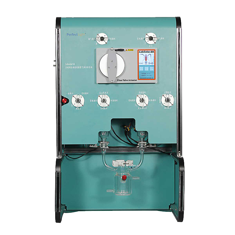
μGAS1000 Micro Gas Reaction Evaluation System is a laboratory equipment developed by BoFeiLei Technology based on years of research and development experience in gas-tight glass reaction systems. It is designed to meet the experimental needs of customers in photocatalysis, particularly in catalytic reactions with trace gases, such as photocatalytic water decomposition and photocatalytic CO₂ reduction.
The main body of the μGAS1000 Micro Gas Reaction Evaluation System integrates software and control unit, gas circulation and automatic sampling module, and reactor module.
1. PC software control, real-time display of reaction process information, and result data
The computer-side software of the μGAS1000 Micro Gas Reaction Evaluation System enables integrated control of the system, gas-phase gas chromatograph, vacuum pump, and achieves fully automated online sampling and injection through a controllable sampling structure. The PC-side control software records experimental information such as experimenter, sample name, light source model used in the experiment, filter model, solution volume, etc. It also records and saves real-time reaction process parameters such as reaction temperature and pressure, achieving paperless experiment recording. Experimental data results can be exported in .xlsx format, and it performs long-term automatic dynamic gas tightness testing. The new reactor design ensures compatibility with any model of vacuum pump.

Figure 1. Software interface of the μGAS1000 Micro Gas Reaction Evaluation System
The upper computer software of the μGAS1000 Micro Gas Reaction Evaluation System uses built-in calculation methods to read test data from the gas chromatograph. It generates reports and calculates data such as gas yield, reaction rate through the software interface. The system can be preheated through the control of the heating module to effectively avoid valve sticking caused by solidification of vacuum grease. The new automated control design ensures compatibility with any model of vacuum pump.

Figure 2. Experimental data exported by the μGAS1000 Micro Gas Reaction Evaluation System
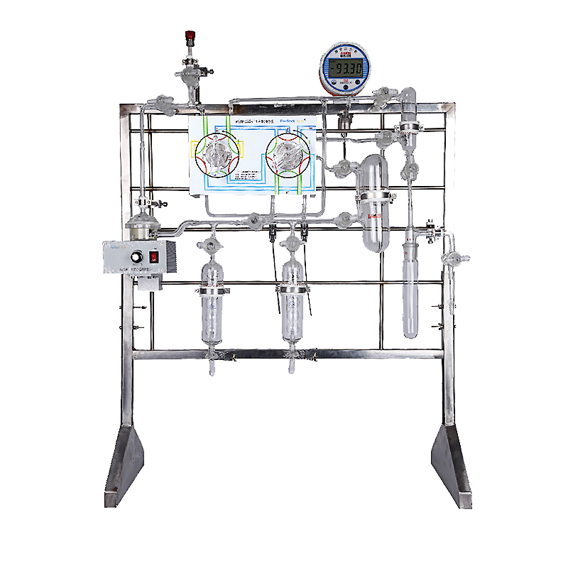
2. Gas circulation and automatic sampling module ensure high stability and accuracy of trace gas analysis
The gas circulation module of the μGAS1000 Micro Gas Reaction Evaluation System mainly consists of a circulation pipeline and a gas circulation power source. The circulation pipeline has a volume of 230 mL and is made of high borosilicate glass. The narrow pipeline has an inner diameter of 3 mm, resulting in low gas resistance. The gas circulation power source uses a passive magnetic drive fan blade pump, which has no risk of hydrogen explosion, does not produce interference from electrolysis water, provides constant circulation power, and ensures that the internal gas pressure of the system is above 3 kPa to guarantee good mixing. H₂, O₂, CO₂, and other gases can be mixed uniformly within 10 minutes, with a linear regression of the calibration curve >0.999. With the same concentration, continuous injection for four times has RSD <3%, achieving scientific-level accuracy.


Figure 3. Schematic diagram and front view of the gas circulation of the μGAS1000 Micro Gas Reaction Evaluation System
The automatic sampling module of the μGAS1000 Micro Gas Reaction Evaluation System uses a patented sampling valve island (patent number: 2022219141302), which enables fully automatic online sampling and injection. Compared to traditional rotating multi-port sampling valves, this sampling valve island has fewer action structures, simple movements, and can effectively avoid air leakage caused by valve movements. The sampling valve island can be equipped with 0.5, 1, 2, 3, 5 mL volume quantitative loops, and the sensitivity can be adjusted according to the different gas production during the reaction. The maximum sampling ratio is 1:88. The sampling valve island can achieve fully automatic background gas function, precisely control the intake of background gas, promote gas circulation, and effectively avoid air interference caused by manual needle injection, affecting the accuracy of experimental data. The μGAS1000 Micro Gas Reaction Evaluation System allows a maximum carrier gas pressure of >0.5 MPa, suitable for gas chromatographs with complex configurations of multiple brands and models.
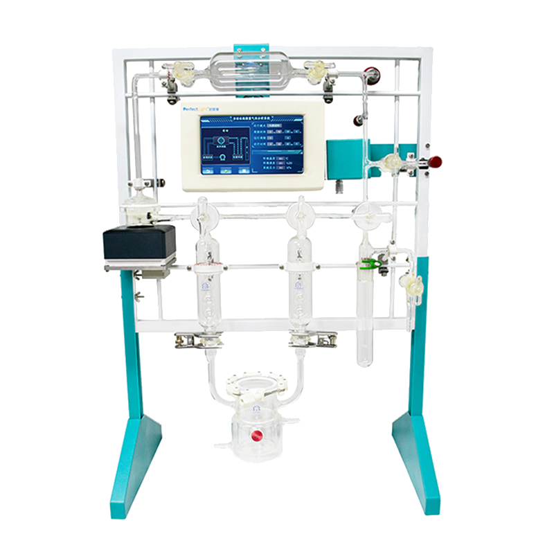
3. Various types of reactors are available to meet the needs of different reaction types
The new type of reactor of the μGAS1000 Micro Gas Reaction Evaluation System can measure, record, and display the real-time reaction temperature at the temperature measuring port through a thermocouple. It can customize reactors for various reaction types, including but not limited to gas-solid phase photocatalytic reactor, gas-liquid-solid phase photocatalytic reactor, photoelectric catalytic reactor, electrocatalytic reactor, and photothermal catalytic reactor, etc.
The new reactor of the μGAS1000 Micro Gas Reaction Evaluation System adopts an integrated design of the temperature control layer and the reactor cavity, with high heat transfer efficiency and high experimental temperature control accuracy, effectively ensuring experimental repeatability.

Figure 4. New reactors of the μGAS1000 Micro Gas Reaction Evaluation System for photocatalytic water decomposition (left) and photocatalytic CO₂ reduction (right)

The new reactor of the μGAS1000 Micro Gas Reaction Evaluation System also uses an inner cone with a flange and an O-ring groove chain-type clip reactor to assist in improving the system's gas tightness. It can meet the experimental needs of trace catalysts and trace reaction liquids. The new reactor adopts a new ball mill pressure sensor and optimizes the sealing process. While ensuring gas tightness, it can be quickly replaced. When a failure occurs, users can replace it themselves without the need for an engineer to come on-site or send it back to the company for repair, saving user time and maintenance costs.
Photocatalytic apparent quantum yield testing
Photocatalytic full water decomposition
Photocatalytic oxygen production rate testing
Photocatalytic hydrogen production
PEC photoelectrocatalytic water decomposition
Electrocatalytic water decomposition
| System Pipeline | |
| Absolute Vacuum Level | ≤0.5 kPa, referenced to absolute zero, to eliminate numerical fluctuations caused by factors such as temperature and humidity affecting differential pressure gauges |
| Pressure Range | 0 kPa~Atmospheric pressure |
| Pipeline Material | High borosilicate glass, high chemical inertness, no adsorption |
| Valve Technology | High borosilicate glass material (no metal parts), using precision grinding process |
| Number of Valves | 6 |
| Vacuum Grease | Imported Apiezon H high-temperature vacuum grease, chemical corrosion resistance, low vapor pressure, low volatility, operating temperature: -10℃ to +200℃ |
| Total System Volume | 440 mL, strong system enrichment capacity |
| Reactor Volume | 210 mL, recommended usage volume: 40~80 mL |
| Gas Storage Bottle Volume | 150 mL, used for system expansion to meet the testing needs of high-yield catalyst activity |
| Pipeline Temperature Control | Both circulation pipeline and injection pipeline can be temperature-controlled, with a maximum control of 120℃ |
| Cold Trap |
|
| Fully Automatic Sampling Module | |
| Sampling Method | The sampling module is located in the system, non-chromatographic sampling, effectively shortening the length of the circulation pipeline and improving gas circulation efficiency; |
| Quantitative Loop | Standard 5 mL, optional 0.5 mL, 1 mL, 2 mL, 3 mL, adjustable sensitivity |
| Full Automatic Background Gas Function |
|
| Allowed Carrier Gas Pressure Range | Maximum 0.5 MPa, suitable for complex configurations of gas chromatographs |
| Gas Circulation Parameters | |
| Gas Mixing Time | H2, O2 mixing time is less than 10 minutes |
| Linearity | Standard curve linear regression R2>0.999 |
| Repeatability | Four consecutive injections, RSD<3% |
| Gas Circulation Power Source | Passive magnetic drive fan blade pump |
| Sampling Method | Patented sampling valve island, fully automatic online sampling module located in the system, non-chromatographic sampling |
| Circulation Pipeline | All circulation pipelines are made of high borosilicate glass, with a narrow inner diameter of 3 mm, |
| Other Parameters | |
| Light Shield | Portable light shield, effectively preventing light pollution; |
| Vacuum Pump | Pumping rate: 6 L/s; |
| Dewar Flask (Optional) | 400 mL Dewar flask, with lid, effectively suppressing liquid nitrogen loss; |
| Overall Dimensions/mm | 660(L)×540(W)×750(H) |
| Software Control Unit | |
| 4.3-inch LCD screen, real-time display of system pressure, ambient temperature, and humidity; | |
| Controlled by upper computer software, powerful functions, high data presentation, full recording of process parameters; | |
| Full record of experimental parameters, real-time saving of process parameters (reaction temperature, pressure, etc.), paperless experiment recording, exportable results; | |
| Built-in calculation methods, can read detection equipment data, directly display reaction rate and other data; | |
| Has fully automatic dynamic air tightness testing function, air tightness can be tested at any time; | |
| Built-in instrument methods, control sampling valve island, realize fully automatic online sampling, injection, background gas injection; | |
| Software can directly control the start/stop of gas chromatograph and vacuum pump; | |
| Can preheat the system to effectively avoid valve sticking caused by solidification of vacuum grease; | |
| Reaction Parameter Monitoring Accuracy | Reaction pressure: 1 Pa, reaction temperature: 0.01℃; |
Standard Curve
H₂: 40~400 μL standard curve linear regression R: 0.9996;
O₂: 20~200 μL standard curve linear regression R: 0.9995;
CH₄ standard gas: 100~1500 μL standard curve linear regression R: 0.9997;
CO standard gas: 100~1500 μL standard curve linear regression R: 0.9995;

Figure 5. H₂ O₂ CH₄ CO Standard Curves
Experimental Testing

Figure 6. Photocatalytic Full Water Decomposition, Oxygen Production, Hydrogen Production, CO₂ Reduction Experimental Results
a) Photocatalytic Full Water Decomposition Reaction: 30 mg photocatalyst, 60 mL H₂O, light power density 1500 mW/cm², Cut 420 filter.
H₂ yield: 27.8 μmol/h, O₂ yield: 14.2 μmol/h, H₂: O₂=1.95
b) Photocatalytic Oxygen Production Reaction: 30 mg photocatalyst, 60 mL H₂O, 10 mM Fe(NO₃)₃, light power density 1500 mW/cm², Cut 420 filter.
O₂ yield: 2.71 μmol/h
c) Photocatalytic Hydrogen Production Reaction: 30 mg photocatalyst, 50 mL H₂O, 10 mL methanol, light power density 800 mW/cm².
H₂ yield: 25.9 μmol/h
d) Photocatalytic CO₂ Reduction Reaction: 60 mg photocatalyst, 55 mL H₂O, 5 mL TEOA, Pt loading 3%wt. Light deposition for 1 hour. Output wavelength: 280 nm~780 nm, intensity 2000 mW/cm². Pre-fill CO₂ to system pressure of 75 kPa, reaction temperature controlled at 15℃, condensation tube temperature at 5℃.
CO yield: 160 μmol/h
(a~d) Mircrosolar 300 xenon lamp light source, reaction temperature 15℃
(a~c) Initial pressure for the reaction 3.0 kPa